 |
| LVDT Transducers |
The LVDT is an acronym used for Linear Variable Differential Transformer. It is an Transformer which is used for measuring linear displacement. LVDT or Linear Variable Differential Transformer is a transducer which comes in the category of Inductive transducers.
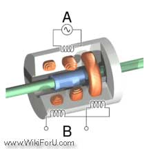
As we know that a transducer is a device which converts one type of energy into some other type of energy. The Linear Variable Differential Transformer do the same. It converts linear displacement into voltage. LVDT is a transformer having one primary coil or primary winding and two secondary coils or winding. There is an iron rod present in the primary and secondary coils. A basic block diagram of LVDT is shown on the left side above.
Also Read: What is Inductor and Inductance?
Working of LVDT (Linear Variable Differential Transformer): The Linear Variable Differential Transformer works on the principal of electromagnetic induction. When we gives supply to the primary winding of the LVDT, a current starts flowing through the primary winding. Due to magnetic property of current, the magnetic lines of force starts flowing around the primary coil, thus a magnetic field is set up around the primary winding. As in general transformers, due to magnetic effect of primary winding, an e.m.f. is also set up in secondary winding when the magnetic lines of force of primary winding cuts (come across contact) the iron rod and secondary winding. This e.m.f. causes a current to flow in secondary winding and this whole process is known as mutual inductance.
Also Read: Construction & Need Of Uninterrupted Power Supply
There are various cases when we moves the iron rod to either left or right side. Lets discuss the effect of different positions of iron rod. The working diagram of these three cases is shown below:

Case 1 (When the rod is placed in Center i.e. Area of contact of iron rod is same with both secondary coils):
When the iron rod is placed in center of both secondary coils then the area of contact of iron rod between two secondary windings is equal, then the equal amount of e.m.f. is developed in the both coils.
Case 2(When the Rod is moved towards the right to the coil S2): When the rod is moves to the right side towards the secondary coil 2 then the area of contact of rod is larger with secondary coil S2 as compared to coil S1. Therefore , more amount of magnetic field cuts the coil S2 and thus more e.m.f. will be induced in the secondary coil S2.
Case 3(When Iron Rod is moved towards the left, to coil S1): When the iron rod is moved towards the coil S1 that is to left side then the contact area of secondary coil S1 will be larger than coil S2. Thus more e.m.f. will be induced in secondary coil S2.


